
Project report: Building a connection from Detroit to Windsor

21 March 2024
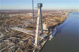
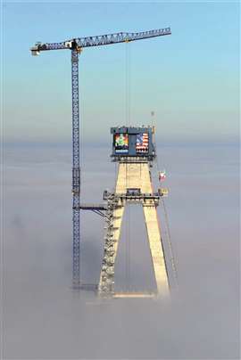 The fully installed stair tower high above the cloud covered river. (Photo: Bridging North America and D.H. Charles Engineering, Inc.)
In October 2020, Universal Manufacturing reached out to D.H. Charles Engineering (DHC) to begin the planning process of providing worker access to the climbing concrete formwork for the bridge piers of the new Gordie Howe International Bridge.
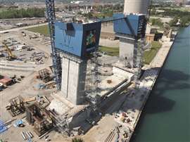 Stage 1 of the stair tower. Set on the ground, it allowed access from grade up to ~215 feet, allowing access to the first series of concrete pours. (Photo: Bridging North America and D.H. Charles Engineering, Inc.)
The stair towers access requirements were to provide secondary access in lieu of elevator access to the climbing formwork, while also addressing emergency egress if the elevators were non-operational. The drawing package, prepared by Universal and reviewed and stamped by DHC, outlined detailed stair tower sections that would be built at grade and hoisted into place as the pier pours progressed in height. Because of this, the stair towers had to have the ability to increase in height along with the piers themselves. Additionally, there was the issue of lateral stability. With a project site directly on the banks of the Detroit River and expected to be in place for years, the scaffold would be subjected to some of the harshest seasonal weather possible.
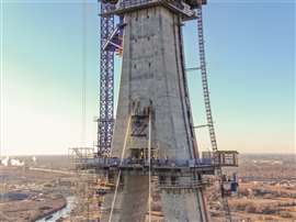
As an added complication, due to the A-frame shape of the piers, for every 1 foot of increased height the piers would translate 2 inches to the side, ultimately topping out over 72 feet away from where they started at the base. Since the stair towers would need to be rigidly tied to the piers for lateral stability, it meant that as the scaffold increased in height, the ties would become both longer and more asymmetrical. Overcoming this critical hurdle would become a key aspect of the scaffold design.
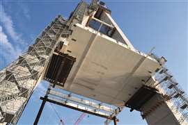 As the piers increased in height, they angled toward each other, ultimately meeting at the top. This created the complex design challenge of large tie distances and tying to a structure whose location changed with height. (Photo: Bridging North America and D.H. Charles Engineering, Inc.)
Planning for height
As our northern neighbor, it should come as no surprise that Canada is one of the top trading partners with the United States. But what can be surprising is the sheer amount of trade that moves between the two: over $664 BN in 2021 alone. Even more impressive is that nearly a quarter of that trade moves over the Detroit River between the Canadian city of Windsor and Detroit, MI. It is for this very reason that a new bridge linking the two gateway cities began in 2004. After more than a decade of planning and preparation, construction of the Gordie Howe International Bridge was started in 2018 by a consortium of construction companies coming together as Bridging North America (BNA). Ultimately, the bridge would span over half a mile, with the iconic silhouette of the bridge being set by two A-shaped piers rising 722 feet above the river.
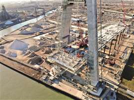
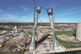 Stair towers during Stage 2, showcasing the complex tie design securing the towers to the angled piers that would be utilized at all 3 phases. (Photo: Bridging North America and D.H. Charles Engineering, Inc.)
In 2020, BNA tasked Universal Manufacturing with providing a solution for worker access to the climbing concrete formwork that would be used to pour the US Main Span bridge pier. Finally topping out at almost 550 feet tall from grade to the junction of the two legs, the height and geometry of the pier design were significant. And while material hoists would be available, the need for a safe, reliable, and fail-safe source of egress for workers throughout the construction phase was critical.
Design factors
Multiple factors had to be considered during the initial design process. Two separate stair towers were needed at the on-set of the project as the space between the two legs of the pier was too great to be bridged between the two climbing forms. Once an elevation of roughly 225 feet was reached on both legs, a walkway bridge was installed on top of the climbing formwork and the South stair tower would continue to rise to the required height of almost 550 feet tall.
 The stair tower fully installed and the new pier nearly at full height. (Photo: Bridging North America and D.H. Charles Engineering, Inc.)
Once Universal Manufacturing and BNA agreed on a general concept, Chris Cox of Universal then reached out to Mark Palmatier of D.H. Charles Engineering. From the outset, a significant aspect of the scaffold design was the sheer height that needed to be reached. At nearly 550 feet tall, just the weight of the scaffold components themselves in a continuous stair tower would exceed the component capacities, even before accounting for any sort of worker live load.
Coupled with that, and possibly the larger design hurdle, was to ensure the stair towers were firmly secured to the pier structures. For a system that would be in place for multiple seasons and subject to some of the harshest environs, a rigid and robust tie system was essential, and became a focal point in the design.
Due to the A‐frame shape of the bridge pier, as the pier legs increased in height, they would slope toward each other and eventually meet at the top. From a scaffold design aspect, this made for an increasingly complex layout and tie situation: as the scaffold got progressively taller, the structure to which the scaffold was tied for laterally stability would continuously pull further and further away. Ultimately, a three-phase approach was determined as the best balance to provide access reaching almost 550-foot-tall. The base of the scaffold would be set on grade and reach a maximum height of ~214 feet.
 The stairs provided a critical emergency egress option for workers at the top of the 550-foot-tall pier. (Photo: Bridging North America and D.H. Charles Engineering, Inc.)
At that point, a steel platform structure would be secured to the bridge pier upon which the Phase 2 stair tower would be set and stretch an additional 157 feet tall. A second steel platform would be anchored to the bridge structure nearly 371 feet above the ground. Reset on this final platform, the Phase 3 stair would reach 173 feet and allow access to the point where the two legs of the A‐frame would meet. For each stair tower resting on platforms, the base was moved over to position the stair tower to address the slope of the pier. The steel reset platforms were ultimately designed by a separate consulting office, so loading and potential design forces that would be imparted by the stair towers were provided to and coordinated with the platform design team.
Once the height and weight of the stairs was managed, focus shifted to the scaffold ties. Set on the banks of the Detroit River, and significantly taller than any structure around, there would be little relief from the harsh winds that can form in the region. This would be especially true for the tallest scaffold of Phase 3.
Reaching for the sky
Not only would it see the full force of wind speeds up to 105 mph, but also at the highest section, the stair tower would be offset from the pier structure nearly 20 feet in two directions. This meant any bracing back to the pier would see intense asymmetric loading with tie lengths exceeding 25 feet long. To ensure the forces that would be collected by the stair tower were accurately tallied, each phase of the stairs was built in a finite element analysis model and analyzed under various wind loading conditions. The models not only considered the height of each built stair section, but also the elevation and duration it would be installed. At each tie location, the maximum and minimum forces were collated and used to calculate worst case loading in both tension and compression.
 Designed to grow as the project progressed, the stair towers provided access to multiple aspects of the bridge, from the bridge deck to the pier formwork. (Photo: Bridging North America and D.H. Charles Engineering, Inc.)
Due to the distances that needed to be covered by the ties, the decision was made early on to utilize modular scaffold trusses as the rigid tie components which were further strengthened by lateral tube and clamp connections between the trusses. Taking advantage of the inherent strength of the double truss ledger in a premanufactured component made installation significantly simpler than attempting the same configuration with individual scaffold tubes. Because the tie lengths and angles varied at each tie location as the pier shifted in relation to the stairs, the bracing at each tie level was modeled, with a total of 26 models by project completion.
DHC took home the 2023 Scaffold & Access Industry Association Industrial Collaborative Project of the Year Award for its work.
STAY CONNECTED


Receive the information you need when you need it through our world-leading magazines, newsletters and daily briefings.
CONNECT WITH THE TEAM